
Multi-element rear wing, air guidance gap and surrounding vehicle body surfaces.
Tesla: How Can a Deployable Rear Wing Balance Styling and Downforce?
Technical problem
A fixed rear wing can add downforce but also increase drag, interrupt the rear body shape and project into the path of a rear impact. This published application describes a wing that can stow, deploy and rotate, with a separate impact-protection function. It is a published application, not a granted patent.
Technical solution
Integrating a multi-element wing with the rear body
The vehicle wing assembly 102 uses a multi-element wing 104 comprising a main wing element 106 and a leading edge slat element 108. An air guidance gap 302 separates the two elements.
In the stowed arrangement described in the application, a step in the upper surface of the main wing blends with the decklid 904, integrating the wing with the rear panel 206 of the vehicle 118. The slat is concealed beneath the rear bodywork. An extension of the liftgate glass can cover the main wing leading edge 144 and the slat, concealing their separation. FIG. 1A identifies the wing elements and surrounding body surfaces; the stowing details are explained in the description and later drawings.
Deploying and rotating the wing with a four-bar linkage
The wing deployment mechanism 110 has a four-bar linkage system 122 on each side. A first link 120 and a second link 308 each pivot from a linkage support element 312 on the vehicle frame 310 and connect to a wing support arm 124. Extending the first deployment actuator 304 moves the wing upward and rearward from the stowed position 202.
In the wing rotation mechanism 314, a second rotation actuator 306 within the support arm changes the angle of the wing. The main wing element 106 and leading edge slat element 108 rotate together, maintaining their air guidance gap 302. A wing controller 316 uses vehicle sensors 318 to coordinate deployment and rotation.
The application describes example targets of deployment in less than three seconds and full angular movement in less than a quarter of a second. Non-back-drivable actuators hold the wing against aerodynamic loads without continuous power. These are disclosed design examples, not verified production Roadster specifications.
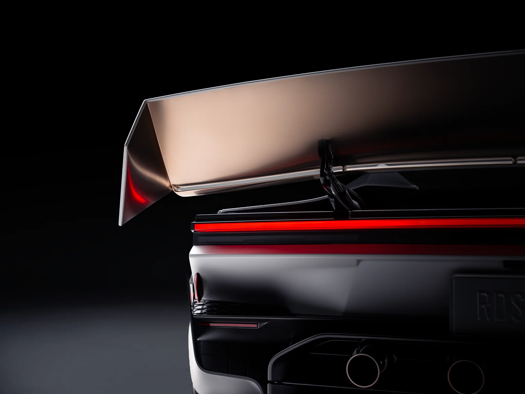
Tesla’s official Roadster close-up shows a raised rear wing and supporting members beneath it. The photograph can be compared visually with the wing and support arrangement in the application drawing. The product view is raised, whereas the comparison drawing shows the stowed mechanism.
Tesla is both the vehicle developer and the applicant. The visible arrangement provides product context, but the photograph alone does not confirm the internal linkage, actuators or impact-protection system described in this published application.
Selecting stowed, low-drag and high-downforce modes
An alternative wing deployment mechanism 110 uses linear rails. A deployment linear actuator 402 acts through a pinned linkage 406 to move a first frame 408 along a first linear rail 404, with a second linear rail 414 providing additional support and guidance. In this arrangement, extending the deployment linear actuator 402 holds the wing in the stowed position 202; retracting it moves the multi-element wing 104 upward and rearward to the deployed position 204.
The wing is connected to a second frame 412 through a pivot 410. Extending the rotation actuator 416 raises the trailing edge and increases the angle of attack. The deployment actuator direction in this linear-rail example differs from that of the four-bar example.
| Mode | Wing position | Aerodynamic purpose |
|---|---|---|
| Road mode | Stowed with the main wing blended into the decklid | Styling and efficiency; partial deployment may improve stability during high-speed cruising |
| Track, low drag (DRS) | Deployed, approximately horizontal | The application describes a stalled gap and reduced slat effectiveness, reducing drag for straight-line acceleration |
| Track, high downforce | Deployed with the trailing edge raised | The slat and main element interact to maintain attached airflow at a high angle of attack, supporting braking and cornering |
DRS stands for Drag Reduction System. Example spacing between the wing elements is 3–15 mm. The application reports development using computational fluid dynamics (CFD), a 50%-scale wind tunnel and full-scale wind tunnel testing. It describes about +350 counts of drag coefficient and −1000 counts of lift coefficient from stowed to deployed, and a reduction of about 250 drag counts when rotating from high downforce to low drag. These values describe the reported development example.
Linear-rail wing mechanism in stowed, deployed and rotated positions.
Retracting the projecting wing in a rear impact
A fully deployed wing projects beyond the rear body. The impact-protection system can use proximity, radar, camera and pressure sensors to detect an imminent or actual rear impact. It commands retraction until the trailing edge 602 aligns with the rearmost profile 604 of the vehicle.
For a center rear impact 608, the wing remains laterally level as it retracts. For a side rear impact 606, it can incline while retracting to reduce the projection on the affected side. Reaching this non-projecting position can be faster than fully stowing the wing. A separately disclosed passive latch can release above a specified impact-force threshold without depending on electronic detection.
The earlier article Tesla: How Skirts Work with Fans (Chinese) examines another approach to active downforce. This application focuses instead on moving and rotating the rear wing.
Rear-impact retraction and inclination relative to the vehicle rearmost profile.
* This article explains how the technology is implemented. It does not interpret patent scope or assess infringement.